国内大型气浮研发生产基地— 采用国内外先进核心技术 —
Nav
Close
Sales hotline:15906188575 051088101158Service hotline:18015950732
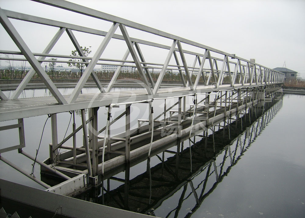
Peripheral drive sludge suction machine is applied for secondary radical-flow style sedimentation tank of sewage treatment plant flow. Its main function is to scrapping the bottom sludge into a group of suction pipe as radical direction layout, then the suction pipes output sludge will be discharged out through center sludge pipe to fit for sludge re-flux or concentrated dehydration. As per the real circumstances, it can be also set the surface scuffing mechanism for collecting pool surface scum which will be discharged outside the pool through the scum funnel
1. Work bridge adopts truss structure with simple design , beautiful appearance, light weight.
2. Maintenance is simple and convenient with low operating costs. Usually using a siphon will set the sludge tank to the center of the sludge discharge pipe, no dynamic seal, to avoid supernatant short flow.
3. Using a new type of mud transfer valve with easy and reliable operation to ensure sludge outlet concentration.
4. Multiplex reducer options:shaft-mounted one has simple and compact structure with easy maintenance; cycloid reducer has high transmission efficiency with competitive cost
5. According to user needs, walking wheel surface material can use engineering rubber wheel (standard), steel wheel, nylon wheel, polyurethane wheel.
6. Electrical components are used outdoor, safe and reliable, can be random control and remote control.
7. The device can be manufactured in a user-specific size. It is possible to provide a flatbed, a slanting basin and a scraper with a large flat mouth nozzle that does not require a collecting plate. Water touched part adopt SS material.
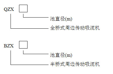
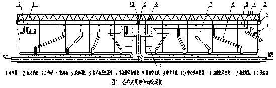
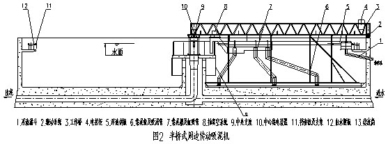
Peripheral drive sludge suction machine can be divided into both siphon and gravity styles as per sludge outlet way due to no seal to get ride of short flow on upper clean liquid . It can be divided into full and half bridge style as per working bridge and siphon tube. Full-bridge one shown in Figure 1, half-bridge one shown in Figure 2.
It is composed of such main parts as working bridge, suction pipeline , siphon tube , sink tank ,vacuum system and center mud tanks (no need it if follows below drawing 3 civil engineering design ) ,center bearing, drive mechanism, collector, electric control box and such optional parts as triangular water outlet weir plates, steady flow tube, slag plate, scum skimming board and other accessories( configure as per demand of customers) .
The working bridge rotates surrounding with the center pool support driven by drive mechanism mounted around it the sludge collecting plates will collect its bottom sludge into each suction port, under function of the liquid level difference, the suction port outlet sludge will be discharge out via sink tank, siphon , center sludge tank, and sludge discharge tube respectively. There is a sludge output adjustable valve on each top of the suction pipe to adjust its flow and concentration. The concentrated scum gathering in the thickener area between its scraper plates and surrounding block plate will be discharge out of the pool via scraping rake.
Full-bridge peripheral drive suction scrapper technical parameters in Table 1.
Half-bridge peripheral drive suction scrapper technical parameters in Table 2.
Equipment civil conditions shown in Figure 3.
Civil conditions see Table 3.
Technical Parameters Table 1
| Model | Pool DN(m) | Water depth(m) | Pool depth(m) | Peripheral speed(m/min) | Power(kw) |
|---|---|---|---|---|---|
| QZX18 | 18 | 2.6~3.6 | 3~4 | 1.2~1.6 | 0.55x2 (Import Reducer0.37x2) |
| QZX20 | 20 | 2.6~3.6 | 3~4 | 1.2~1.6 | |
| QZX25 | 25 | 2.6~3.6 | 3~4 | 1.5~1.8 | |
| QZX30 | 30 | 2.6~3.6 | 3~4 | 1.5~1.8 | |
| QZX35 | 35 | 2.6~4.1 | 3~4.5 | 1.5~1.8 | |
| QZX40 | 40 | 2.6~4.1 | 3~4.5 | 1.5~2 | |
| QZX45 | 45 | 2.6~4.1 | 3~4.5 | 1.5~2 | 0.75x2 (Import Reducer0.55x2) |
| QZX50 | 50 | 2.6~4.1 | 3~4.5 | 1.5~2 | |
| QZX55 | 55 | 2.6~4.1 | 3~4.5 | 1.5~2.2 | |
| QZX60 | 60 | 2.6~4.1 | 3~4.5 | 1.5~2.2 |
Technical Parameters Table 2
| Model | Pool DN(m) | Water depth(m) | Pool depth(m) | Peripheral speed(m/min) | Power(kw) |
|---|---|---|---|---|---|
| BZX18 | 18 | 2.6~3.6 | 3~4 | 1.2~1.6 | 0.55 (Import Reducer0.37) |
| BZX20 | 20 | 2.6~3.6 | 3~4 | 1.2~1.6 | |
| BZX25 | 25 | 2.6~3.6 | 3~4 | 1.5~1.8 | |
| BZX30 | 30 | 2.6~3.6 | 3~4 | 1.5~1.8 | |
| BZX35 | 35 | 2.6~4.1 | 3~4.5 | 1.5~1.8 | |
| BZX40 | 40 | 2.6~4.1 | 3~4.5 | 1.5~2 | |
| BZX45 | 45 | 2.6~4.1 | 3~4.5 | 1.5~2 | 0.75 (Import Reducer0.55) |
| BZX50 | 50 | 2.6~4.1 | 3~4.5 | 1.5~2 | |
| BZX55 | 55 | 2.6~4.1 | 3~4.5 | 1.5~2.2 | |
| BZX60 | 60 | 2.6~4.1 | 3~4.5 | 1.5~2.2 |
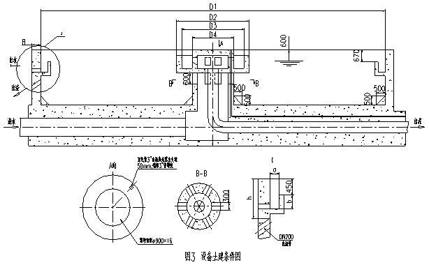
Equipment Civil Conditions Dimension Table 3 (Unit:mm)
| D1(m) | 18 | 20 | 25 | 30 | 35 | 40 | 45 | 50 | 55 | 60 |
|---|---|---|---|---|---|---|---|---|---|---|
| D2 | 4200 | 4500 | ||||||||
| D3 | 3600 | 3900 | ||||||||
| D4 | 2400 | 2700 | ||||||||
| H | 3~4 | 3~4.5 | ||||||||
| a | 400 | 450 | 500 | 550 | 600 | |||||
| b | 450 | 500 | 600 | |||||||
| h | 1800 | |||||||||
 WeChat
 Mobile